-
 UnknownEditor
5Bandwidth is probably the most important question as some approaches are only good for narrow band.
UnknownEditor
5Bandwidth is probably the most important question as some approaches are only good for narrow band.
Also, you should consider if the outputs need to have the same transmission phase...
Steve -
 Franklin1
0Thank you for responding and sorry for the lack of details,
Franklin1
0Thank you for responding and sorry for the lack of details,
The center frequency must be 1.575GHz, Insertion Loss <5dB, Isolation >20.0dB, Phase Balance at the output <5 degrees, VSWR over passband <1.5 : 1, amplitude Balance at output <1dB.
Since I last posted I have thought about doing a 4 output wilkinson power divider. I would love to know your thoughts -
 Justin Magers
0Seems like a lumped element solution might be possible at 1.5 GHz. Maybe "<5 dB insertion loss" means that the 5 dB in addition to 6 dB loss from the 4-way split.
Justin Magers
0Seems like a lumped element solution might be possible at 1.5 GHz. Maybe "<5 dB insertion loss" means that the 5 dB in addition to 6 dB loss from the 4-way split. -
Franklin1
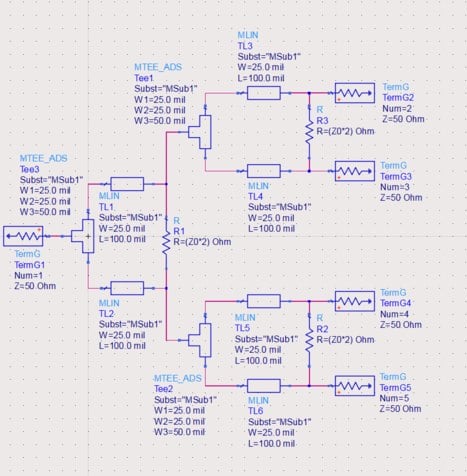
0Attached is what I have so far using ADS.
My next step is to figure out where to go from here to reach the design specifications. How can I figure out what to change the widths and lengths of the lines to? And when I run my simulation and create my graphs, what should I be looking for within the S parameters? What should I be graphing together?Attachment design2
(49K)
design2
(49K)
-
UnknownEditor
5You need to make the lines 1/4 wave long at center frequency
You should plot S11, S22, S23 and S24. The rest of the parameters will be repeats of these due to symmetry. You can make a goal of -20 dB at band center for all of them.
The widths of the lines should correspond to 71 ohms. ADS should be able to calculate the line widths and quarterwave lengths for you.
That should get you started
This seems like a homework assignment...
Steve


Welcome!
Join the international conversation on a broad range of microwave and RF topics. Learn about the latest developments in our industry, post questions for your peers to answer, and weigh in with some answers if you can!
Categories
- About Our Site
- Antennas
- Applications
- Biological Effects and Applications
- Calculators
- Communications
- Computer Aided Design
- EDA Software
- Emerging Applications and Technology
- Employment
- Field Theory
- Filters and Passives
- General Questions
- High Power
- History
- MMIC and RFIC
- Packaging and Materials
- Radar
- Sources and Receivers
- Test and Measurement
More Discussions
- Terms of Service
- Useful Hints and Tips
- Sign In
- © 2026 Microwaves 101 Discussion Board