-
 UnknownEditor
4That is a great question! I took a look around, some designs just show a three-port box with labels...
Maybe a picture like this?
https://en.wikipedia.org/wiki/Orthomode_transducer#/media/File:Orthomode-transducer_01.jpg
Sorry I am not a huge help, I'll try to ask an antenna person.
Steve -
 CMoncsko
1Symbols are usually derived from either the mathematical symbolism of the operation they perform or from the physical shape of the common implementation of mechanism.
For an OMT, there isn't really a graphical description of the mathematical operation and the physical shape of an OMT is really just a bunch of rectangles...
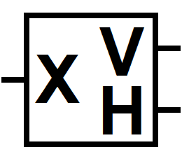
I think in this case it makes sense to fall back to a Box with a reference to port functions, i.e. A square bounding box with an O, X, or large + to represent the dual-pol port. The O would be for circular waveguide (but sometimes people will use a square waveguide), or perhaps use an X for cross-polarized or use a large plus for a physical representation of horizontal and vertical polarization superimposed together)
The polarized ports can simply be described by a V or an H to clearly indicate the two single-pol ports. (Or L and R if you're doing circular polarization...)Attachment OMT Symbol
(2K)

-
 lauryfriese
0A commonly used schematic symbol for Orthomode Transducers (OMTs) in block diagrams and circuit diagrams is a combination of two crossed waveguide symbols. Here is a simplified representation:
```
______
| |
----| |----
|______|
```
The above symbol represents the OMT, with two waveguide ports crossing each other orthogonally. The horizontal line represents one polarization (e.g., horizontal), and the vertical line represents the other polarization (e.g., vertical). The incoming or outgoing signals are connected to the appropriate ports of the OMT.
Welcome!
Join the international conversation on a broad range of microwave and RF topics. Learn about the latest developments in our industry, post questions for your peers to answer, and weigh in with some answers if you can!
Categories
- About Our Site
- Antennas
- Applications
- Biological Effects and Applications
- Calculators
- Communications
- Computer Aided Design
- EDA Software
- Emerging Applications and Technology
- Employment
- Field Theory
- Filters and Passives
- General Questions
- High Power
- History
- MMIC and RFIC
- Packaging and Materials
- Radar
- Sources and Receivers
- Test and Measurement
- Terms of Service
- Useful Hints and Tips
- Sign In
- © 2026 Microwaves 101 Discussion Board


