-
 sMall
0I am designing an LNA at 24 GHz using the discrete RF FET CE3520K3. I am implementing this design on 10 mil Rogers 4350B substrate. Just by looking at the S parameters (attached), I can see that the FET itself is inherently unstable at frequencies below 11GHz. So, I have been trying to make the LNA stable by various methods, but have been unsuccessful. The only way I could get unconditional stability at all frequencies is by adding a shunt resistor at the gate of the FET. I know that this increases the noise figure and the resistor has lot of parasitics at 24GHz, which might kill the design. I have looked for information on stabilizing very high frequency LNA design using discrete FETs in many textbooks and all over the internet, but could not find any information. Any suggestions are very welcome.Attachment
sMall
0I am designing an LNA at 24 GHz using the discrete RF FET CE3520K3. I am implementing this design on 10 mil Rogers 4350B substrate. Just by looking at the S parameters (attached), I can see that the FET itself is inherently unstable at frequencies below 11GHz. So, I have been trying to make the LNA stable by various methods, but have been unsuccessful. The only way I could get unconditional stability at all frequencies is by adding a shunt resistor at the gate of the FET. I know that this increases the noise figure and the resistor has lot of parasitics at 24GHz, which might kill the design. I have looked for information on stabilizing very high frequency LNA design using discrete FETs in many textbooks and all over the internet, but could not find any information. Any suggestions are very welcome.Attachment CE3520K3v02n_2-26G_2V_10mA.s2p
(21K)
CE3520K3v02n_2-26G_2V_10mA.s2p
(21K)
-
 SM4RZW
024 GHz microstrip bandpass filter on output is mentioned here:
SM4RZW
024 GHz microstrip bandpass filter on output is mentioned here:
https://electronics.stackexchange.com/questions/440004/has-anyone-designed-a-low-noise-amplifier-in-the-ism-band-24-ghz-using-the-dis -
 UnknownEditor
5I took a fast look at that FET but could not stabilize it in the ten minutes I spent, without messing up the minimum noise figure. I hope to mess with it later, I don;t like it when instability wins.
UnknownEditor
5I took a fast look at that FET but could not stabilize it in the ten minutes I spent, without messing up the minimum noise figure. I hope to mess with it later, I don;t like it when instability wins.
Does anyone have any experience with balanced LNAs? A friend of mine claims that almost automatically stabilizes the circuit but I am skeptical.
Steve -
 Osman Ceylan
0In my previous job, we had the same problem with a SiGe transistor. We copied the application circuit at the datasheet, but it was really bad regarding wideband stability. A low-pass type network including biasing circuit worked well. But it degraded noise performance a little. If you are not a big customer, usually vendors do not reply your e-mails.
Osman Ceylan
0In my previous job, we had the same problem with a SiGe transistor. We copied the application circuit at the datasheet, but it was really bad regarding wideband stability. A low-pass type network including biasing circuit worked well. But it degraded noise performance a little. If you are not a big customer, usually vendors do not reply your e-mails. -
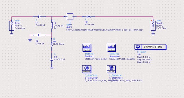
 jmcghee
0I've had a lot of experience using FETs like these down in L band to squeeze out the best noise temp possible for atmospheric instrumentation. The issue is these FETs have lots of available gain at low frequencies, so you have to give that gain somewhere else to go. The "easiest" method which I've had success with is using series-C, shunt-L, and maybe another series-L depending, on the input to match gamma_opt, and AC couple that shunt-L to ground with an RF decoupling cap good in your band of interest, and and also terminating it to 50 ohms with a "DC" decoupling cap. The gate voltage is fed through. In my case here, with 10 minutes of futzing around, I get series C of 0.22pF, shunt L of 1.78nH, and RF decoupling of 0.5pF. In this case, it wasn't quite enough for unconditional stability, but adding a 5 ohm series resistor at the drain fixed that. Degrades NFmin by a 0.037 dB, but stabilizes it everywhere. I didn't go so far as adding the drain bias network. The idea is that the FET will see the RF ground through the 0.5pF more than it sees the noise from the termination resistor in your band of interest. Hope that helps.Attachment
jmcghee
0I've had a lot of experience using FETs like these down in L band to squeeze out the best noise temp possible for atmospheric instrumentation. The issue is these FETs have lots of available gain at low frequencies, so you have to give that gain somewhere else to go. The "easiest" method which I've had success with is using series-C, shunt-L, and maybe another series-L depending, on the input to match gamma_opt, and AC couple that shunt-L to ground with an RF decoupling cap good in your band of interest, and and also terminating it to 50 ohms with a "DC" decoupling cap. The gate voltage is fed through. In my case here, with 10 minutes of futzing around, I get series C of 0.22pF, shunt L of 1.78nH, and RF decoupling of 0.5pF. In this case, it wasn't quite enough for unconditional stability, but adding a 5 ohm series resistor at the drain fixed that. Degrades NFmin by a 0.037 dB, but stabilizes it everywhere. I didn't go so far as adding the drain bias network. The idea is that the FET will see the RF ground through the 0.5pF more than it sees the noise from the termination resistor in your band of interest. Hope that helps.Attachment Capture1
(29K)
Capture1
(29K)
-
UnknownEditor
5jmcghee... any possibility you could sketch that out?
Also, is it possible to add a bandpass filter that is designed so that it makes it "nearly impossible" to present an unstable load to the part? Maybe the unstable region is on the open side of the Smith Chart, and you make sure that the device sees a short circuit. I have never analyzed this, maybe you can't get there without some real resistance.
Thanks!


Welcome!
Join the international conversation on a broad range of microwave and RF topics. Learn about the latest developments in our industry, post questions for your peers to answer, and weigh in with some answers if you can!
Categories
- About Our Site
- Antennas
- Applications
- Biological Effects and Applications
- Calculators
- Communications
- Computer Aided Design
- EDA Software
- Emerging Applications and Technology
- Employment
- Field Theory
- Filters and Passives
- General Questions
- High Power
- History
- MMIC and RFIC
- Packaging and Materials
- Radar
- Sources and Receivers
- Test and Measurement
More Discussions
- Terms of Service
- Useful Hints and Tips
- Sign In
- © 2026 Microwaves 101 Discussion Board